User and Developer Reference
All info about this project
About
Mechanical Blender pretends to be a software solution for mechanical desing, also suitable for architectural, affordable for small companies that cannot afford an existing pro application, or any company or person that wants to be free and own the software used for its business.
Blender
Blender is an opensource source software powerfull in creation of 3D content with a huge comunity of users and developers headed by Blender Foundation. Check blender.org for more reference.
Lisence
Mechanical blender is according to blender copyright.
New features added are subject to the GPL license, which you can download from the web: http://www.gnu.org/copyleft/gpl.html
Mechanical Blender comes with ABSOLUTELY NO WARRANTY. Is distributed in the hope that it will be useful and IT IS PROVIDED "AS IS" without warranty of any kind. The entire risk as to the quality and performance of the program is with you.
User ManualBlender Basics
For any blender basics you shoud refer to Blender manual or any of multiple tutorials and courses that can be found on the web.
General ImprovementsUse of Custom Transform Orientation when creating data
When a Custom Transform Orientation is selected, the data is created using it.
Units
Blender Units, sense
Object Units
to Scene Blender Units definition, will be translated to the object unit definition. Can be enabled / disabled and it's independent for each object, so we can work in inches on one object, and mm on another one. The inputs value, are also considering the object units.
Force Units
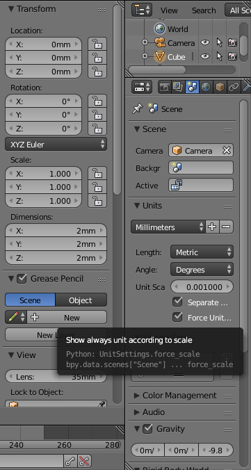
Blender allows to set up a unit system. A force flag is added to not change the unit scale acording to value. So if set all values will shown with same unit (eg 10mm will not be transformed to 1cm)
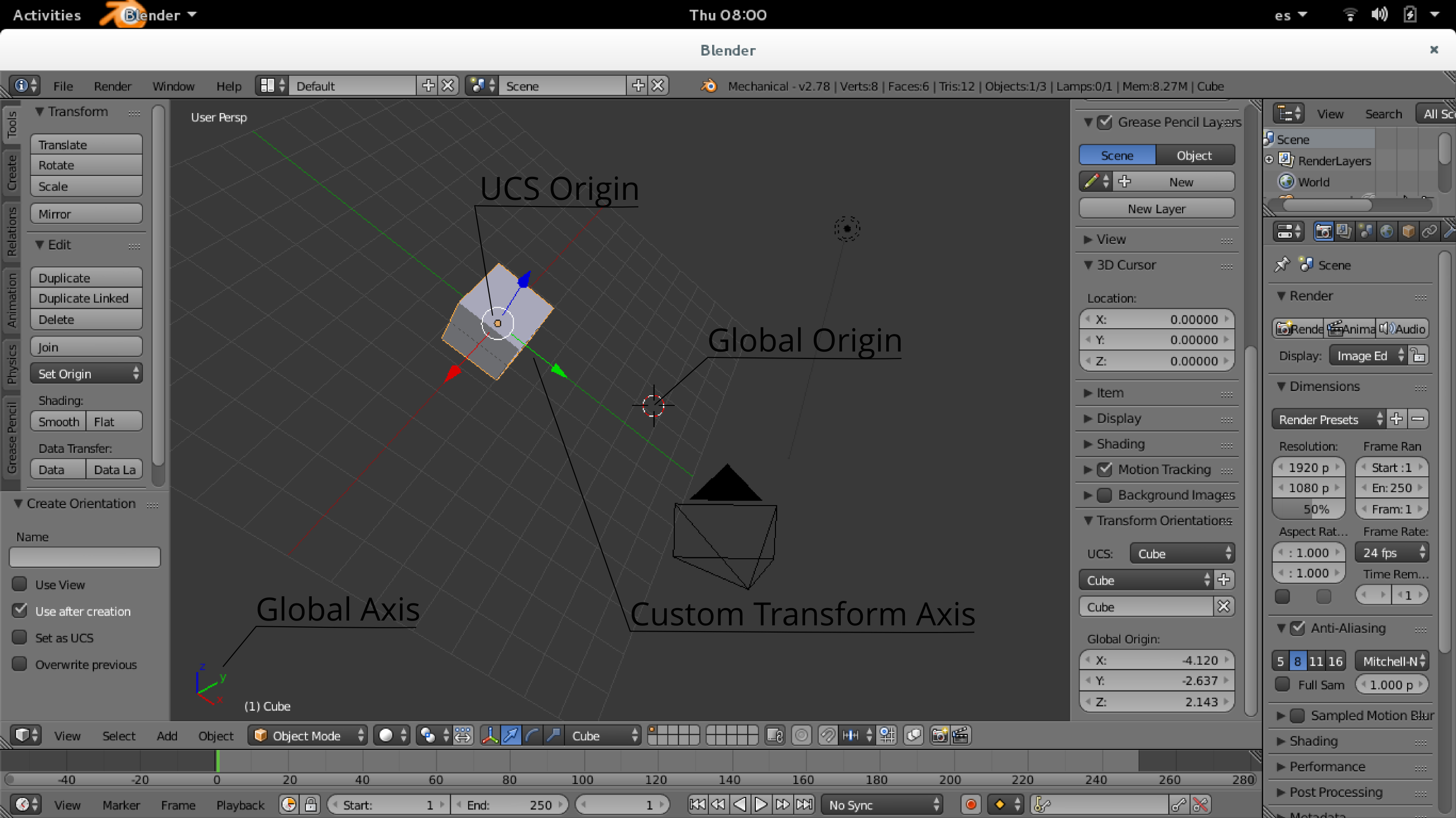
User Coordinates Spaces
Mechanical blender enhances custom transorm orientations, adding a origin point to them.
UCS are created like transform operation CTRL+ALT+SPACEThe UCS select allows to select it. When selected, the working origin is set on the ucs Origin Also the oriented views (Left, Rigth, Bottom) views match the UCS, afecting also to grid snapping.
Snapping tools
Snap tools are designed to place obects with precision related to mesh data (vertexs, edged,faces).
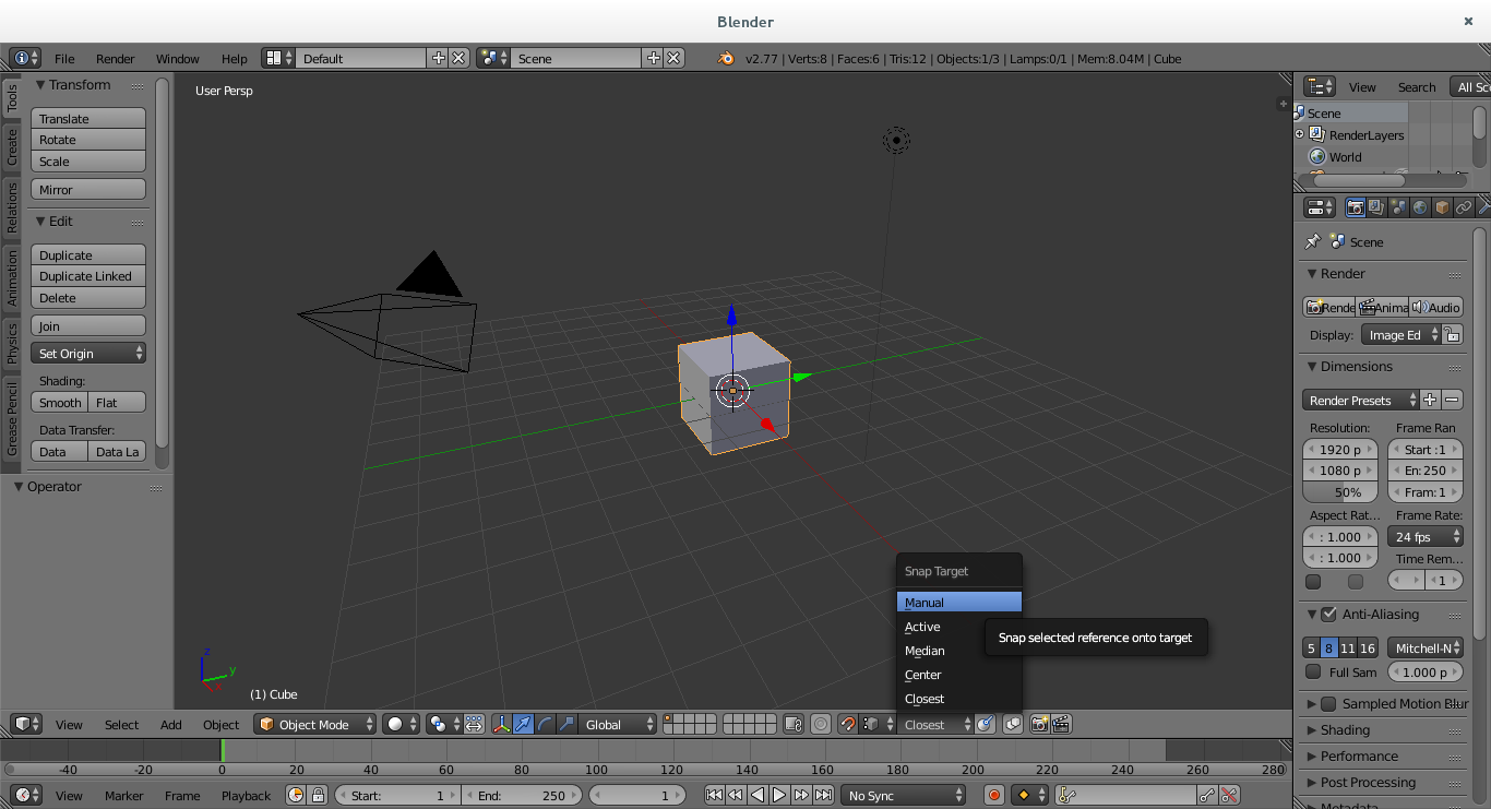
User can change the Snap Element during operation using
Manual Snap Target
Allows to select a point for reference on transform, can be selected during tranform using BKey
It can be set by default seting as Manual on Snap Target list. Then before starting the transform, user input is required.
On rotation transforms, user can use Wto perform the transform using the axis resulting of start-center-end_point.
Multiple Snap Targets
In the same way you can specify more than one snap point (mostly used to get a mid point) you can select more than one target pressing Awhen the snap target is shown with a circle.
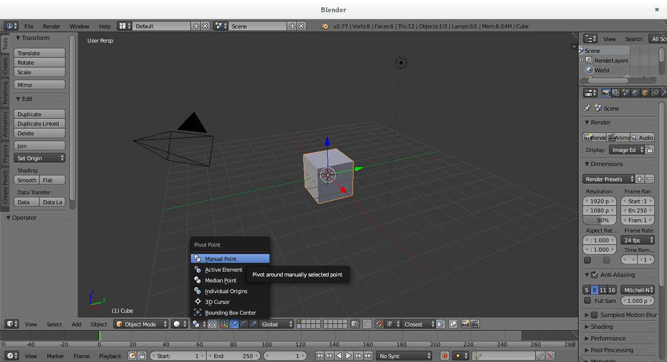
Manual Pivot Point
During rotations and scale transforms, allows to select a point used as center transform, can be selected during tranform usingCKey
It can be set by default seting as Manual on Pivot Point list. Then before starting the transform, user input is required. if Snap Target is set as default, then pivot point is first requested.
Snap Elements
Mechanical blender new type of snap elements to allow precise placements.
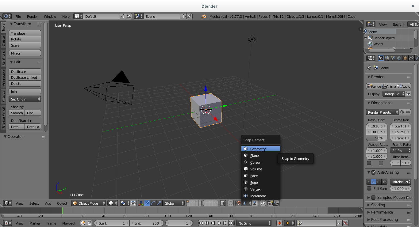
Snap to Cursor
As the cursor can be placed with precision we have enabled the option to use it as snap point.
Snap to Plane
Use a reference plane as snap element
Snap to Geometry
Mechanical blender allows snaping to detected geometry
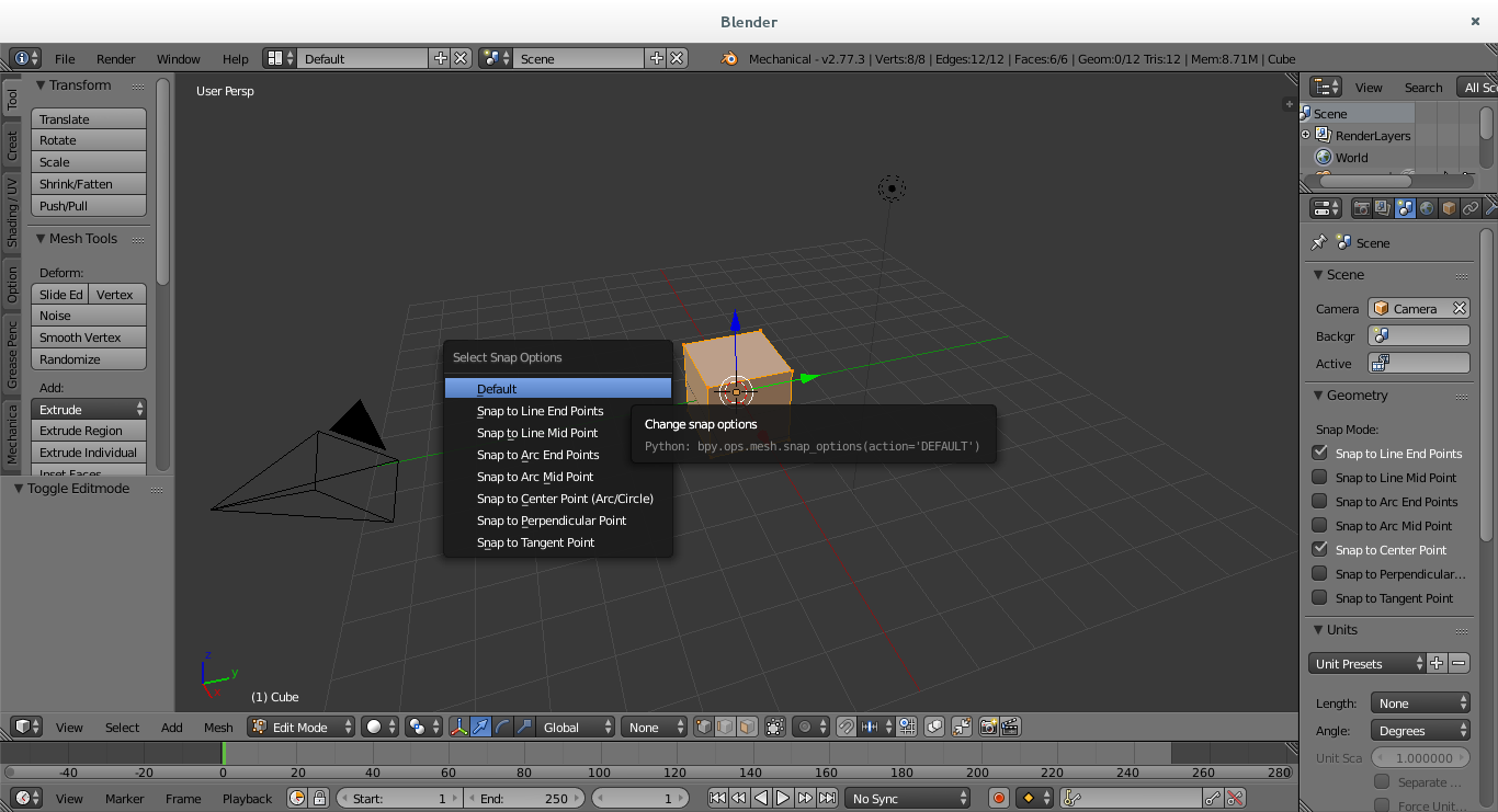
There are this possible snaps
Line end points
-
Line mid point
Being calculated over the geometry entity, the colinear contiguos edges are considered a line, so the middle point is not and edge mitpoint in this case.
-
Arc end points
-
Arc mid point
-
Center point
Center of circles and arcs.
-
Perpendicular
the snap if set from the snap_target to the entity. It is disabled for closest, as depends on the snap_point itself
In case of circle or arc, the snap point is the intersection with the entity and the line from center to the snap_target. It needs booth points to be in the same plane.
-
Tangent point
the snap if set from the snap_target to the entity. It is disabled for closest, as depends on the snap_point itself
it needs booth points to be in the same plane.
They can be selected by default on scene settings. In case of need a non default snap geometry type, can be overrided using the SHIFT S shortcut and select one, or return to default values.
Transform improvements and toolsMove around the scene during transform
Freely move around the scene when a transform operator is running
Creating multiple data
During transform operations, multiple data can be creating pressingM. It can be enabled by default using the UI icon shown in the screenshot.
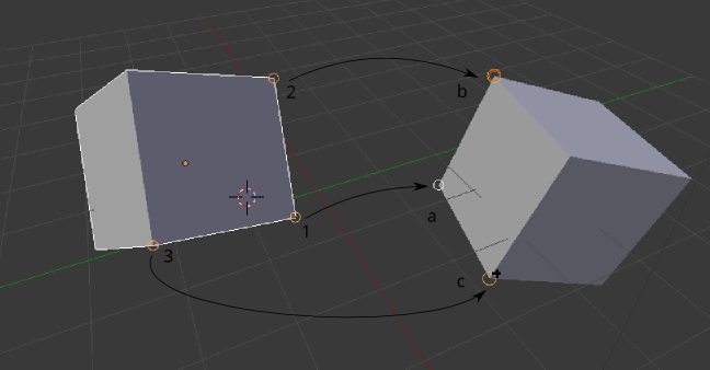
Match Tool
The match tools allow to match a point, an axis, or a plane to another one, works on Object and Editmode.
In order to select targets, you must have enabled a element (Eg, vertex, edge, face) and snapping enabled.
-
Select the geometry that will be applied.
Execute the operator
-
Select a first reference point (1)
-
Select a second a reference point(2), or Middle Mouse Buttonto continue with one point
-
Select a third a reference point (3), or Middle Mouse Buttonto continue with two point
-
Select the match for first reference (a) - translation betwen points
-
if two or more references are set, select the match for second reference (b) - axis alingment
-
if three references are set, select the match for third reference (c) - plane alingment
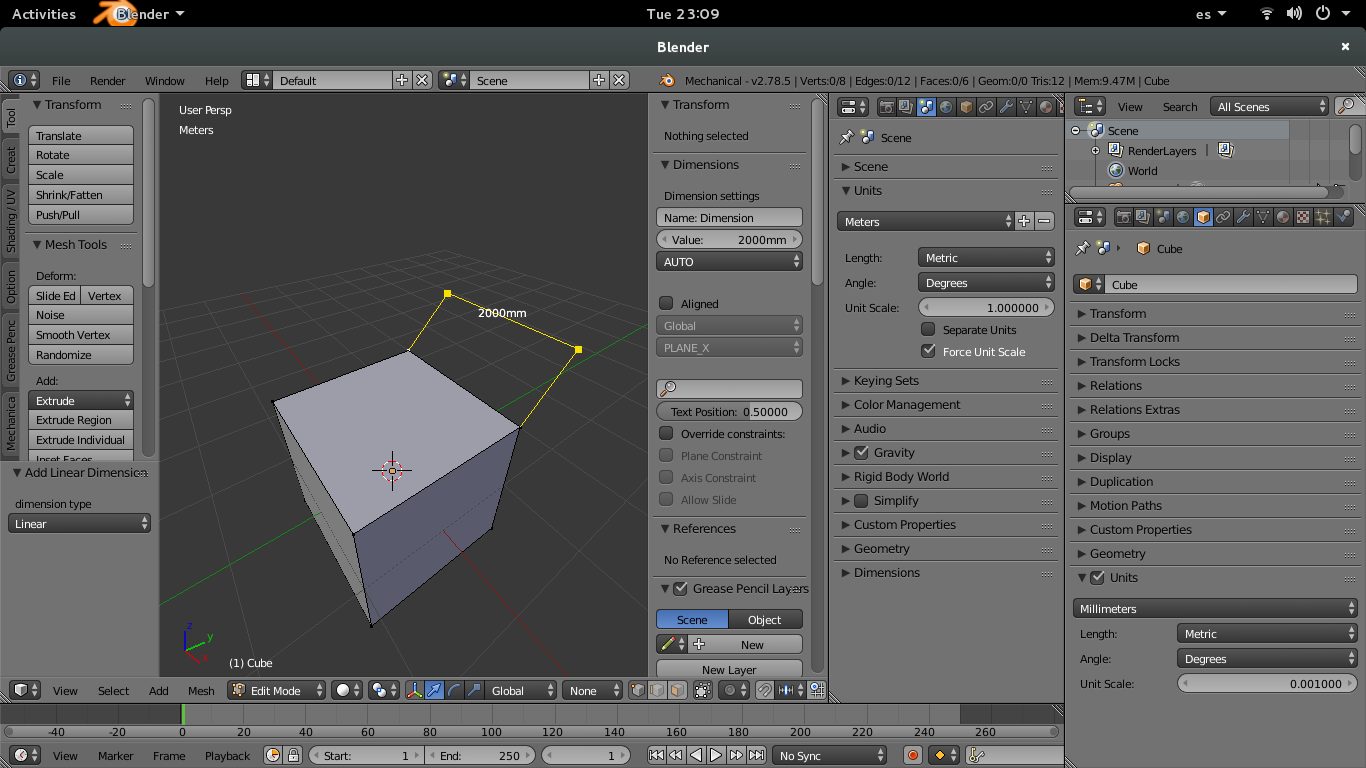
Mesh Dimensions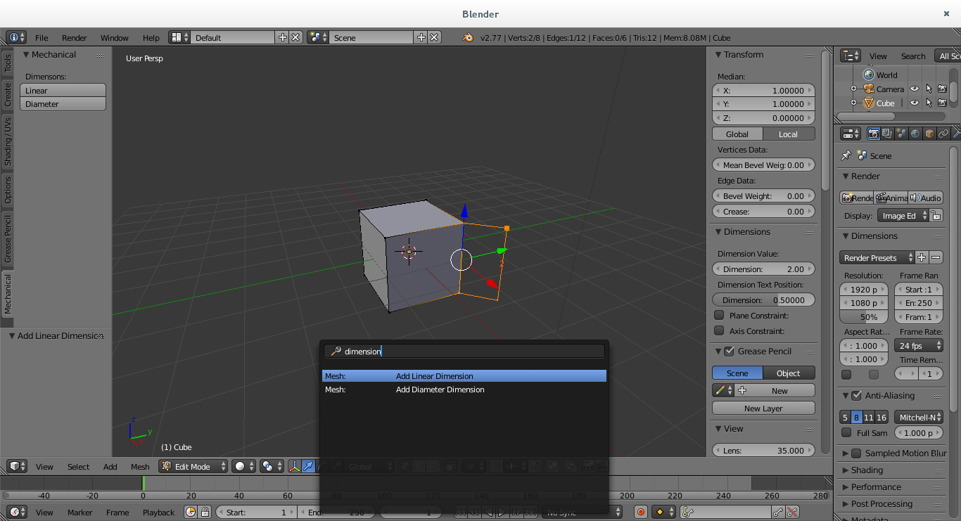
Dimensions are intented to get visual information and modify the mesh acording to it's value.
Mesh geometry can be changed by changing dimension value. This can be done on dimension properties or just typing the value using the numeric pad when a dimension is selected.
The side on wich the mesh is modified is represented with a big point. This point depends on wich side of the dimension number is clicked for selection. Both points are select if just clicked on the middle.
In order to allow selection of dimensions, user can use the CTRL+TAB and select dimensions or vertices
Dimension select also select al related data to the dimension
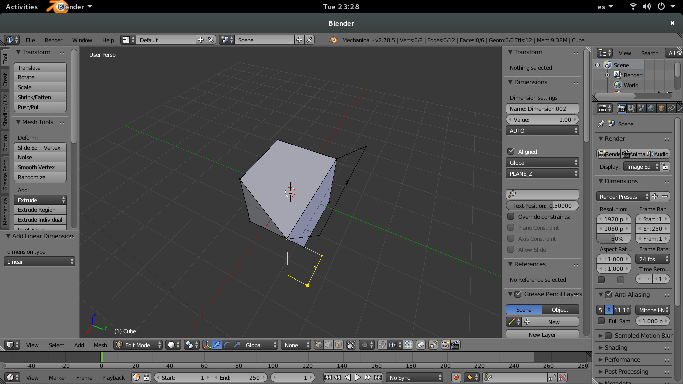
Linear Dimensions
Betwen two vertices
Related vertices get the same transform.
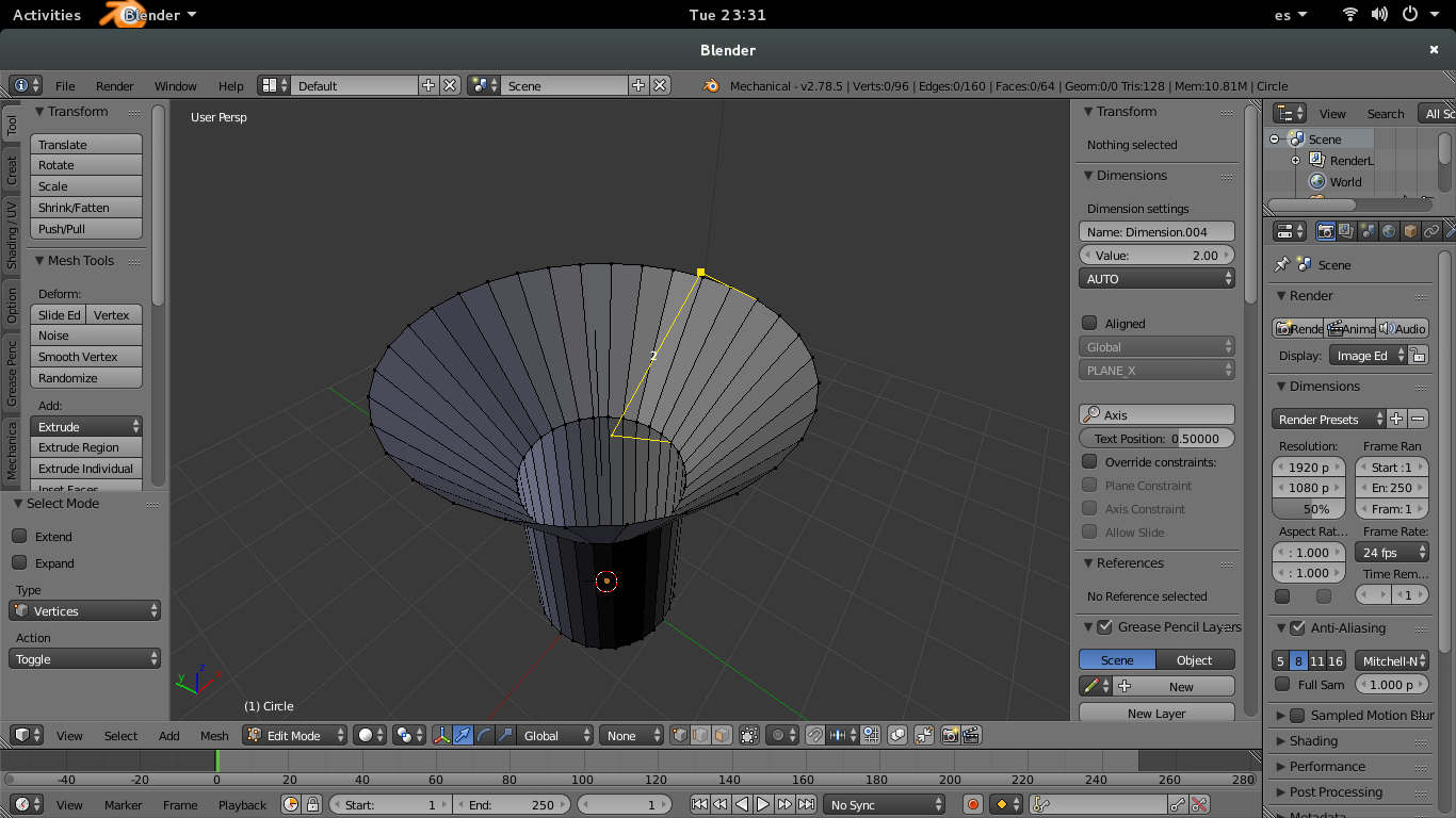
Diameter and Radius Dimensions
More than 3 vertices that equidist to one point (center).
The center of dimension is computed from the first 3 vertices selected, and the dimension value is the distance from first selected vertex to center.
Related vertices are applied the distance of the dimension from the dimension axis.
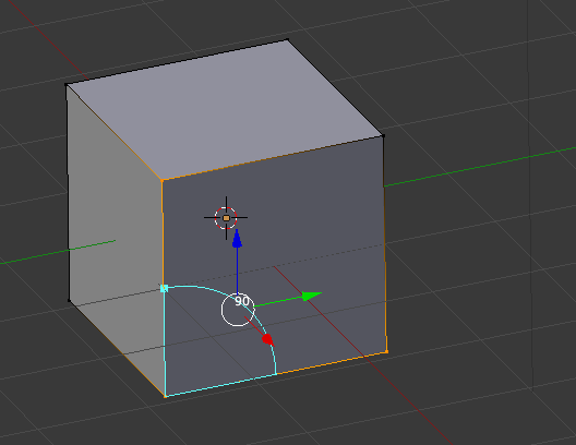
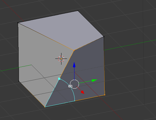
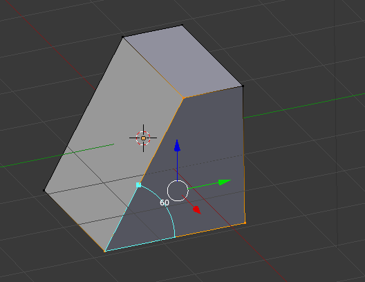
Angle Dimension from 3 Points
Angle between 3 points, being the second point selected the common vertex.
Related vertices are rotated the dimension value around dimension axis.
Angle dimension can modify concentric data, if extra data defines 2 vertices to compute the center.
Angle Dimension from 4 Points
Angle between 4 points, the center is the intersection between ab and cb (selected in the order a,b,c,d)
Related vertices are rotated the dimension value around dimension axis.
Angle dimension can modify concentric data, if extra data defines 2 vertices to compute the center.
Dimension automatic constraints.
Can be changed for selected dimension on N panel under dimensions on EditMode
- Plane Contraint
- On linear dimensions:
If enabled Vertices from faces that have the normal on translation direction, and containt the vertice translated on it's plane will also be considered as related.
- For angle Dimensions:
if enabled Vertices from faces that have the normal on same direction than the result axis between rotation axis, and edge being rotated and containt the vertice translated will be considered as related
- On linear dimensions:
- Axis Constraint
- Diameter dimensions
If enabled, Vertices that are concentric to dimension center at same distance will also be affected.
- For angle Dimensions:
Needs extra data to define center and axis
if enabled, Vertices that are concentric to center at same distance than first vertex selected will be affected.
- Diameter dimensions
- Allow Vertex Slide
- For angle Dimensions
if enabled, the vertices being translaed due to angle change can slide in order to not modify the normal of the other faces, so other angles will not be changed.
- For angle Dimensions
Examples
Default;
No constraints enabled;
Automatic plane constraint;
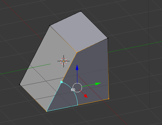
Allow edge slide constraint:
Dimension around Axis
Specifiying andaxis to a dimension, the dimension value will afect to all vertices that are concentric to axis. this allows fast and precise modification of lathe parts.
Aligned Dimension
Linear Dimensions can be aligned to X Y or Z plane of a transform orientation. The second point of the dimension is projected on the defined plane containing the first dimension point
Dimension Parameters
Can be changed for selected dimension on N panel under dimensions on EditMode
If more than one dimension is selected, the change applyes to all dimensions selected.
- Dimension Value
Display and changes the dimension value
The dimension value also can be changed using the numeric pad once the dimension is selected.
- Complementary Angle
Only for 3Points dimensions
Allows to work with the complemtary angle, calculated with the inverted vector from first to second point
- Aligned Dimension
- Dimension Axis
- Dimension Text Position
Display and changes the position of text on dimension, percentually
- Override Constraints
Allow generic settings for automatic constraints to be set specific value for selected dimension(s). The options not enabled for the selected dimension will be disabled.
- Plane Constraint
Overrides plane contraint if allowed
- Axis Constraint
Overrides axis constraint if allowed
- Allow Vertex Slide
Overrides Allow vertex slide constraint if allowed.
Modifying related data.
There are some ways to modify related data along with changes applied for a dimension
Have the vertex that should be modified selected when modifying the dimension value
Create with more than necessary vertices. Extra vertices are considered related
Use Automatic constraints.
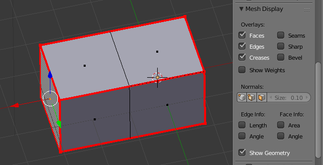
Display Mesh Dimensions
Options found on Display on Properties Panel Nfor 3DView affecting to objects not being edited.
- Show Mesh Dimensions
Shows dimensions for all objects
- Mesh Dimensions on selected
Shows dimensions only for selected objects, assumes Show dimensions for all objects to be set.
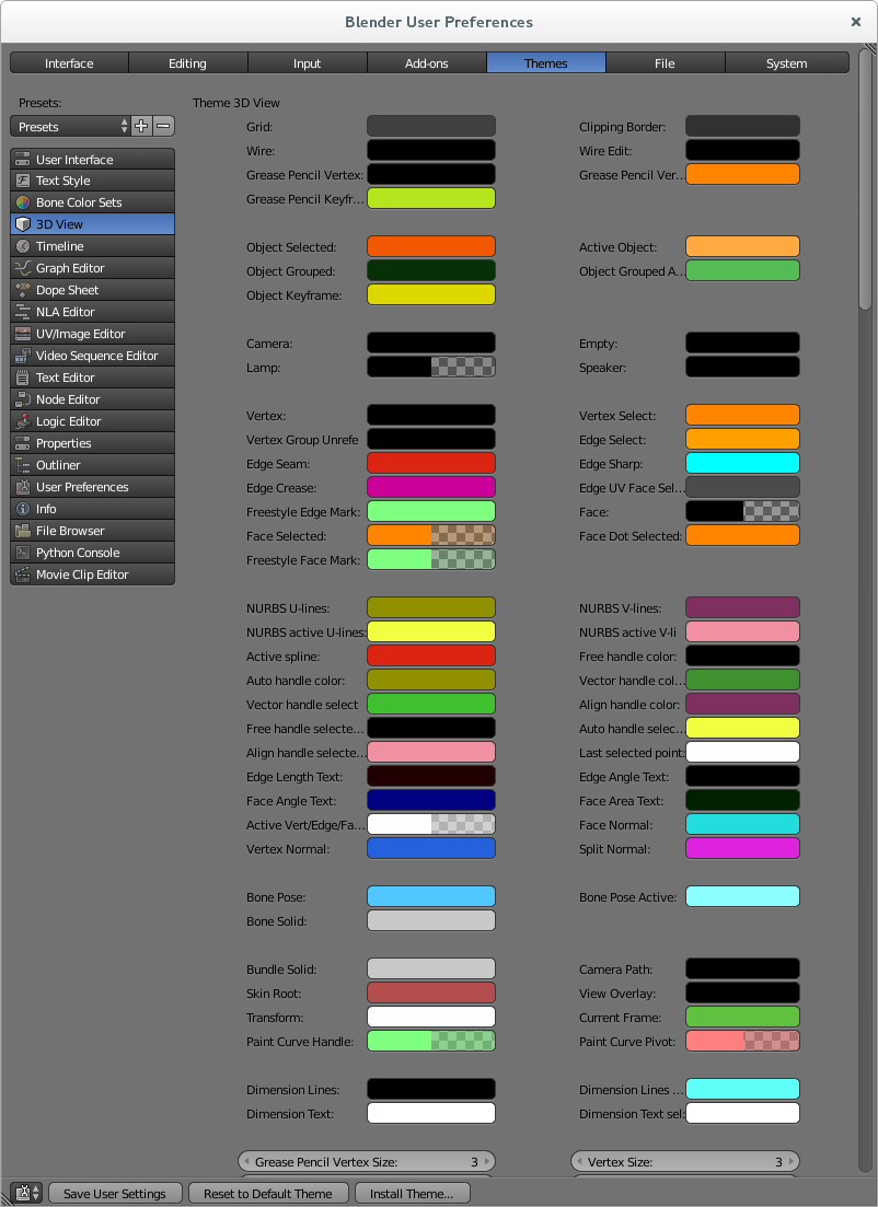
Dimensions Customization
Dimensions colors can be customized on Blender User Preferences CTRL+ALT+U> Themes > 3D View
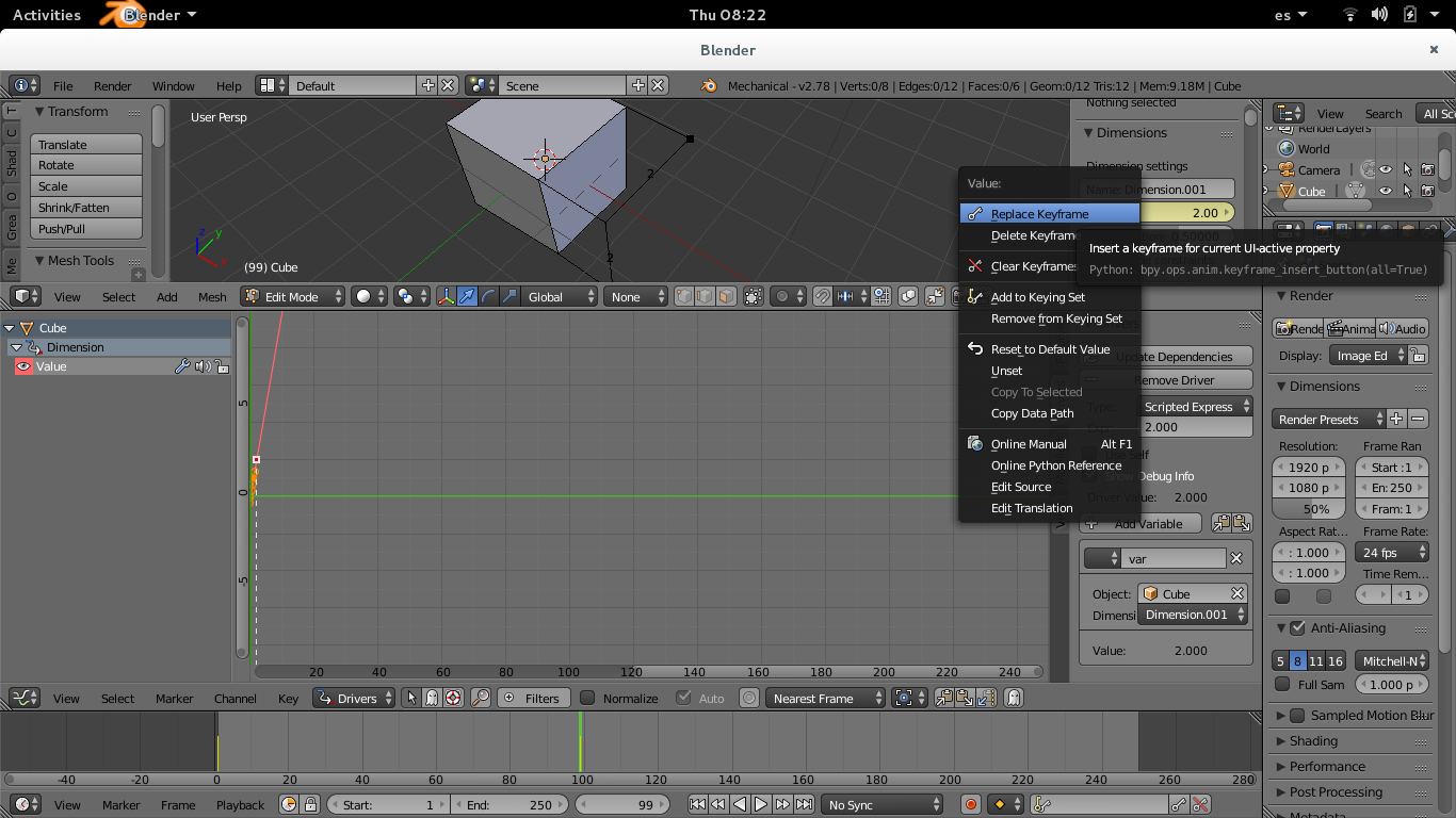
Dimension Animation and Drivers.
The dimension value can be set as driver, driver target, or set keyframe values on it.
Works as other values that can be animated, rigth click over the field.
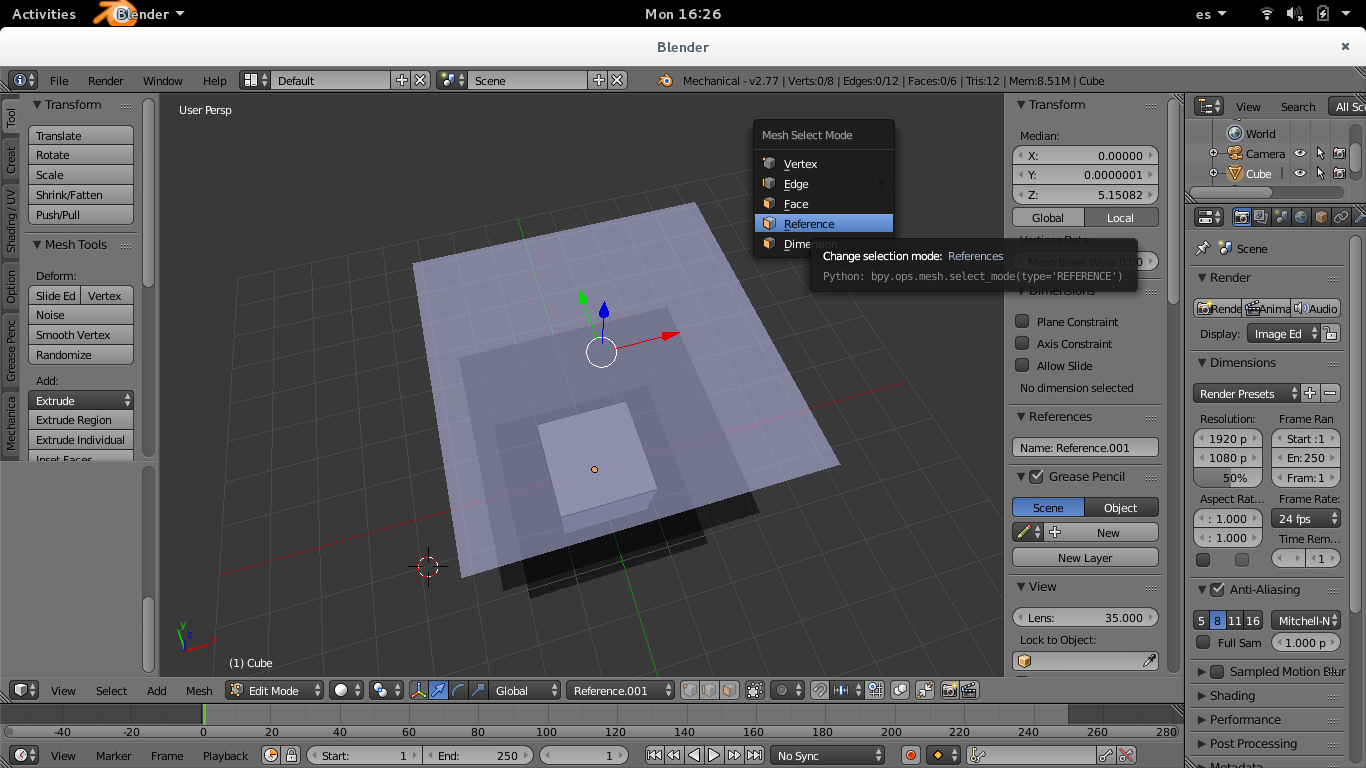
Mesh Reference Objects
References are a new kind of object on the mesh, you can work similary as you work with the other elements (verts, edges, faces)
References are allowed to be used as snap element, so can be selected using CTRL+SHIFT+TAB shortcut or on the list shown on head bar.
In order to allow selection of references, user can use the CTRL+TAB and select references.
Planes
The plane is defined by four (3+1) points that are cannot be selected, by can be transformed as other elements.
On editmode, reference planes can be created using the "Add reference plane" operator.
If there is no selection, the plane is created with a size acording to grid, at 3D cursor position.
if there is 1 vertex selected, the plane center is set to this point
it there is 2 vertices selected, the plane center is set at midpoint of vertices. The X vector is defined by this two points, starting at first point selected.
It there are 3 or more vertices selected, the first 3 are used to create the plane. The first two vertices are used to define de X vector, and 3r one the side of Y vector.
If a face is selected, the vertices of the face will be used to create it.
Axis
A reference axis, is defined by at least 3 concentric points.
On editmode, referen axis, can be created using the "Add referene axis" operator
Axis can be used to specify a dimension as concetric.
Reference Properties
Found on 3D View Propertines panel N
Reference Name: Name for the selected reference.
Creating Custom Transform Orientations from planes
User Can create a transform orientation from a selected plane, using the shorcutCTRL+ALT+SPACE
Also it can created selecting the option "Create Transform orientation on operator properties. This is disabled by default.
The name of the transform orientation matches the plane name, and at the moment is not related (there is no relationship between plane and transform orintation).
Set plane as input.
a reference plane can be set to force input on it, afecting to vertices created. To do this, just select in the head bar.
The plane selected as input, will be drawn in a blue color, more ligthed if it's also selected.
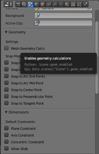
Geometry
Application detects geometry on the mesh, based on edges.
It's computed each time user get's into edit mode and It's partially recomputed each time mesh it's modified: current geometry is checked and updated, on mesh changes. Due to performance reasons, it's not computed during transform operations.
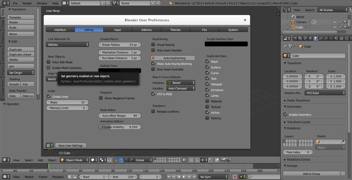
Geometry calcs can be enabled/disabled on scene settings and individually on each object, with a default setting found on User Preferences for new objects This allows to get normal functionality with objects with lots of mesh data that is not necessary to scan for geometry entities
Entities detected- Lines
Edges that pertain to more than one complanar faces are not considered.
On edge is considered a line if does not pertain to another entity, considering previous point.
- Circles
- Arcs
They are set from at least 2 continuos edges not colinear, with a small angle for each edge from center set to 18 degrees
Edges that pertain to more than one complanar faces are not considered.
On edge is considered a line if does not pertain to another entity, considering previous point.
They are set from at least 2 continuos edges not colinear, with a small angle for each edge from center set to 18 degrees
Visualization of detected elements can be enabled on 3D View properties.
Info about geometry detected is shown on stats, indicating the total of geometry entities detected and the number of entities selected.
Geometry select
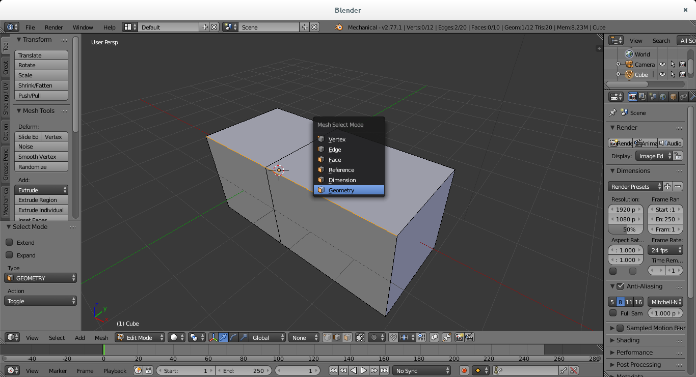
Geometry can be selected selecting "Geometry" as Select Mode using CTRL+TAB shortcut.
Select is based on edge select. The geometry gets selected, and selects the edges is composed from, and the vertices. As transform operations are based on vertexs, you can apply any transfrom on the geometry selected.
Solid Mode
On development
Python APIMesh
We have added this properties to mesh
- Mesh.total_dim_sel
- Mesh.total_ref_sel
- Mesh.references
Developers
The development is shared to comunity on github.
AdvancedIdentify a file created using mechanical blender
Files written with mechanical blender contain custom data(as dimensions)
The file can be identified if it contains the string MECHANICAL in the fileglobal struct.
TODO list
Allow to create a dimensions from python
Allow dimensions to be modified via Python script
Solve last element duplicated when repeting a macro operator
Credits
All the people that contributed in Blender and the Blender Comunity